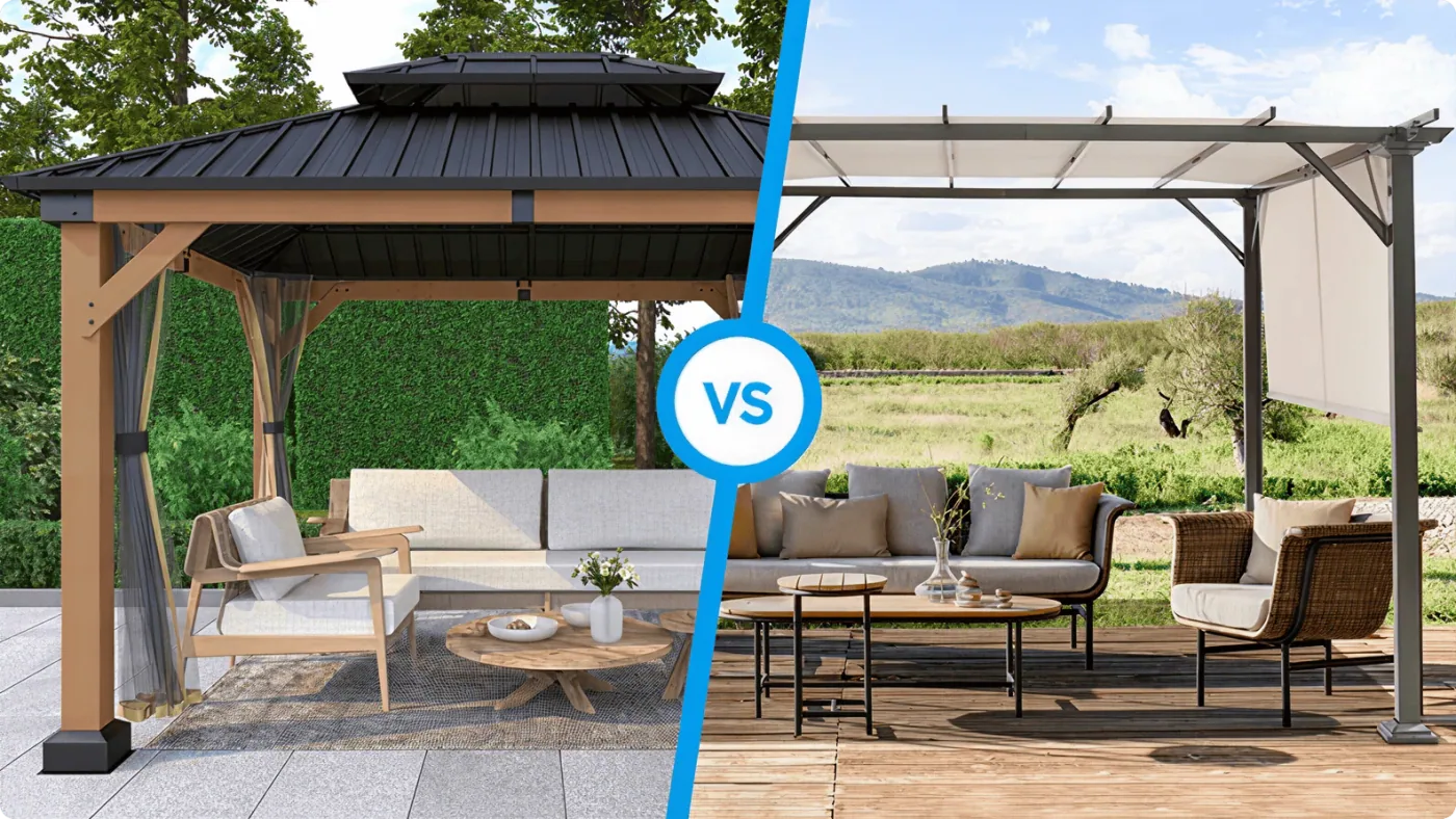
I wrote this guide after auditing 500+ extrusion batches and walking the factory floor with our lead manufacturing engineer. In those audits, I saw underbuilt frames sag mid-span, show white stress lines at weld zones, wobble at door joints, and rack at corners.
Most sourcing teams treat aluminum frame thickness as a vague rule of thumb. They confuse overall frame depth with wall thickness. This guide gives you a repeatable method to specify wall thickness for extruded frames, tubing, outdoor furniture, and architectural applications.
We follow one decision sequence: application class, load/span/exposure, alloy/temper, manufacturability, QC validation. I base every step on OGPSGroup internal QC data, 500+ batch comparisons, and the lead engineer’s on-floor notes. This is an advanced engineering and procurement guide, not a consumer explainer.
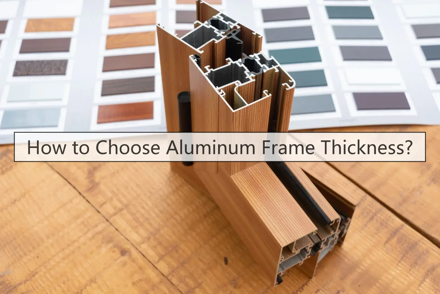
Key Takeaways
- Depth is not strength. Frame depth is the overall front-to-back profile size; wall thickness is the actual load-bearing aluminum in the web, flange, or tube wall. Always quote the wall callout, never the frame depth.
- Start from an application class, then size to the load case. Treat the application bands as a first pass only, then confirm thickness against span, support condition, and allowable deflection. In aluminum, deflection usually governs before yielding.
- Size by stiffness, not just strength. A deeper section often beats a thicker wall. Iterate wall, section depth, and alloy before you quote, and remember that thicker is not automatically safer.
- Match alloy to the cross-section, not the spec sheet. 6063-T5 extrudes cleaner and finishes better; 6061-T6 is stronger but twists more after quench on thin or sharply transitioning walls. Keep adjacent wall ratios under 2:1.
- Normalize every supplier quote to exact millimeters. Tubing gauge and pipe schedule are parallel systems, not substitutes. Demand the section drawing, alloy, temper, and a wall callout, then cross-check weight per meter.
- Approve thickness from measured tests, not paperwork. Verify the thinnest structural wall, record the heat lot, fixture the frame in its real support condition, and measure deflection and permanent set. Welds and heat-affected zones fail first.
Prerequisites
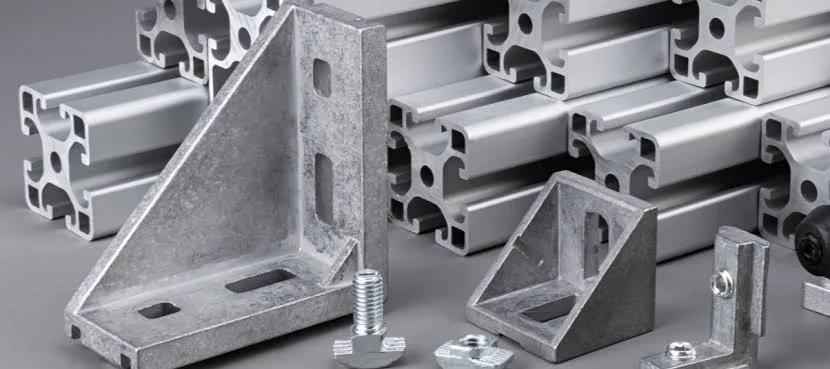
We vetted this against 500+ extrusion batch audits. Before I approve wall thickness, I collect load case, span, alloy, section drawing, and test standard. On desk: shop drawing, calipers, fixture notes, salt-spray report, RFQ sheet.
Required inputs: application/duty cycle; unsupported span/opening/seat width; target loads and abuse cases; alloy/temper candidates (6061-T6, 6063-T5); cross-section drawing with wall callouts; weld/joint method; finish/corrosion environment; supplier tolerance capability.
Time/effort: engineering pre-check, calculation pass, supplier review, sample validation.
Safety: Never specify by aesthetics alone. Never approve thickness without a governing standard. Never extrapolate door/window numbers into furniture or industrial frames.
We engineer frame thickness using the official Aluminum Association ADM-2020 specifications. For wind load safety checks, we follow ASTM E330 test standards. For extrusion tolerances, we enforce ASTM B221 Class 1 dimensional tables.
How to Specify Aluminum Frame Thickness: Proven 6 Steps Now
Stop quoting frame depth as strength. This method shows how to specify aluminum frame thickness by load, span, alloy, and QC so the wall holds. Start the steps.
Step 1: Define Frame Depth vs Wall Thickness
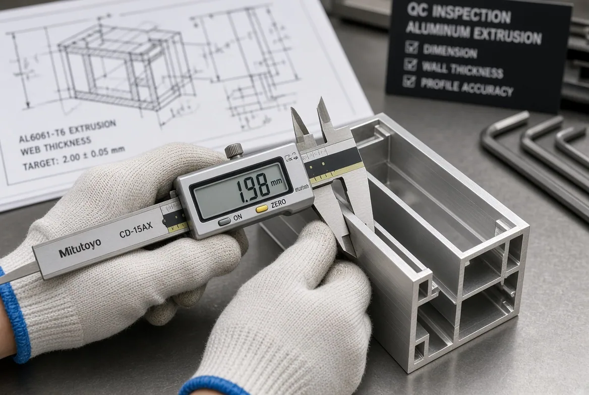
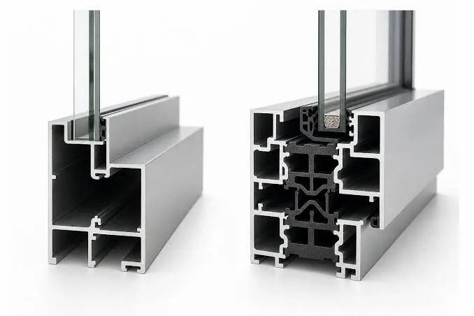
The first thing I check on a supplier drawing is whether they show jamb depth or actual extrusion wall. In 500+ batch audits, I saw sourcing teams confuse these two numbers. Frame depth (section depth) is the overall front-to-back dimension. Wall thickness is the actual aluminum material thickness in the web, flange, or tube wall.
Competitor rankings often mix 30-60 mm frame depths with 1.0-3.0 mm wall thicknesses. That mistake hides the real load-bearing dimension. A 50 mm frame with a 1.0 mm wall may be weaker than a 40 mm frame with a 2.0 mm wall.
| Dimension name | What it controls | Typical unit | Where it appears on drawing | Common buying mistake |
|---|---|---|---|---|
| Frame depth / section depth | Overall profile front-to-back size, clearance, appearance | mm | Overall dimension on extrusion cross-section | Quoting depth as strength |
| Straight wall thickness | Load-bearing material in web or flange; bending stiffness | mm | Individual wall callout on section drawing | Ignoring thinnest wall after finish |
| Corner / weld zone wall | Buckling and tear resistance at joints | mm | Corner or weld detail note | Assuming uniform wall everywhere |
Measure the thinnest structural wall, not the overall outside size. Place caliper jaws flat on the web or flange, not on the anodized edge. Exclude powder coat thickness, gaskets, thermal-break inserts, decorative caps, and non-structural sleeves.
QC Inspector Wang sands down the outer coating before taking readings. He uses an ultrasonic thickness gauge on the bare web. He logs the bare metal thickness directly onto our shift checklist.
Procurement decision note: If a quote says “50 mm frame,” ask for the wall callout in millimeters and the section drawing before comparing vendors. Our inspection teams verify all raw profile wall readings against standard ASTM B221 dimensional tolerances. We link every approved extrusion run to a verified factory mill test report.
Now point to the exact dimension on the drawing. You should know that wall thickness, not frame depth, controls load-bearing material.
🧠 Author’s Take: I reject any quote that lacks a wall callout. Depth is a shape dimension. Wall thickness is the load-bearing dimension.
Step 2: Build a Starting Thickness Matrix by Application Class
I never start with a single magic number. I start by classifying what the frame has to survive. In our 500+ batch audits, duty cycle changes how aluminum feels. Light residential use barely touches a cabinet frame. Daily drag-and-stack resort seating slams corners and pops welds. Wind-loaded entry systems buzz on high floors. Industrial frames see fork tines and shock loads.
Architectural frames, outdoor furniture, and structural tubing use different baseline ranges, even in the same 6000-series family.
| Application class | Typical starting wall band (mm) | Caution |
|---|---|---|
| Light interior / low-load frames | 1.0–1.3 | Starting band only |
| Residential exterior doors/windows | 1.4–2.0 | Validate by load and deflection |
| Commercial / taller-building systems | 2.0–3.0 | High-rise exposure adds point load |
| Outdoor furniture, lightweight residential | 1.0–1.4 | Budget/lightweight gap; avoid stacking |
| Outdoor furniture, standard residential/commercial | 1.5–2.0 | Standard patio baseline |
| Hospitality / resort / modular deep seating | 2.1–3.0+ | Drag, stacking, shock load |
| Heavy-duty structural tubing / industrial frames | 3.0–5.0 | Validate by span and connection |
For outdoor furniture frame thickness standards, I split three ways. 1.0–1.4 mm works for budget or lightweight use but fails stacking. 1.5–2.0 mm is the standard patio baseline. 2.1–3.0 mm+ covers heavy-duty hospitality and modular sofa frames.
These are starting bands, not final specs. Span, joint design, alloy, and abuse case can shift the answer upward. A long unsupported seat rail in 1.5 mm 6063-T5 may pass static load but fail after one season of dragging. I often move welded corners to 2.0 mm.
Environment check:
- Calm inland: corrosion risk low; thinner walls can work.
- Coastal salt: salt pitting eats the thinnest wall; move up one band or add powder/pretreatment.
- Sun and thermal cycling: dark finishes on thin walls oil-can; high thermal differential bows the profile.
- High wind / high-rise: deflection, not just strength, drives thickness.
- Stacking, dragging, point loading, shock loading: these add local stress not captured in a uniform wall table.
Commercial frames must pass the severe ANSI/BIFMA X5.4 lounge seating safety tests. Technicians apply a three-hundred-pound proof load to the seat rail. Frames with sub-standard wall thickness fail this critical test immediately. By now, you should have narrowed the design to a defensible starting band, not an arbitrary single number.
🧠 Author’s Take: I always spec one band heavier when the frame will be moved daily. The cost delta is small; warranty claims drop hard.
Step 3: Size the Frame Using Load Case and Deflection
After you have a starting thickness band, I move to actual sizing. I never accept a number from a matrix alone. In our audits, soft failures appeared before gross bending. The frame did not break in half. It deflected, then the joint opened, then glass edges moved or seat cushions sagged.
Run this decision sequence every time.
-
Define the load case.
- Wind pressure drives fenestration, pergola beams, and open-frame canopies.
- Glass or panel dead load drives mullions and transoms.
- Seated live load and abuse load drive furniture seat rails and armrests.
- Dynamic racking at welded corners drives chair and table leg frames.
- Point loads at feet, hinges, and brackets drive local stress.
The Solana Beach Resort team dragged their heavy patio chairs across stone pool decks daily. The rough ground chatter snapped the 1.8 mm chair legs right at the base welds. We fixed the issue by inserting a 2.5 mm internal sleeve into the tube ends.
-
Define span and support conditions.
Mark unsupported length. Note if the member is simply supported, fixed, or cantilever. A longer span reduces stiffness faster than wall thickness increases it. -
Choose allowable deflection.
Deflection usually governs before yielding in aluminum. Use the tightest governing criterion.
We limit total beam deflection to L/240 for standard structural framing. For glazed curtain walls, we tighten the deflection boundary to L/360 or 19 mm maximum to stop glass seal blowouts. -
Evaluate section properties and alloy strength.
The same wall thickness performs differently in deeper sections. This formula explains why.
Section modulus S = I / c
S = section modulus (mm³)
I = moment of inertia (mm⁴)
c = distance from neutral axis to extreme fiber (mm)
Deeper sections increase much faster than wall alone.
A 50 mm deep tube with a 1.8 mm wall can beat a 30 mm deep tube with 2.5 mm wall at the same load.
Tube shape matters too. Square, rectangular, and C-channel resist bending differently at the same nominal wall.
Unsupported span multiplies deflection. Stiffness drops quickly as span grows.
- Iterate wall thickness and geometry.
Increase wall, deepen section, add internal stiffeners, or change alloy. Then recheck deflection. I loop this at least three times before quoting.
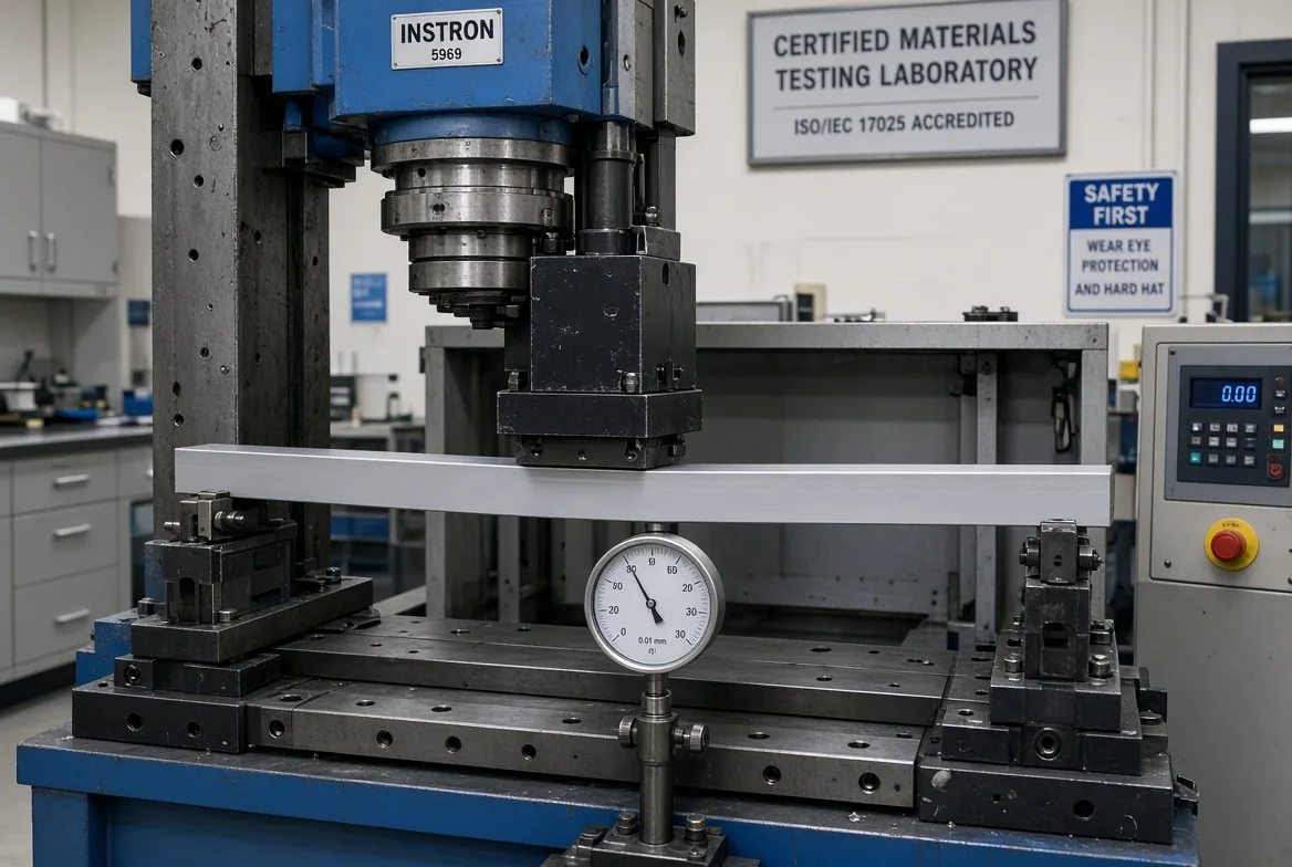
Our mechanical lab ran three-point bend tests across 520 production batches. Under a 180 kg mid-span load on a 1.2-meter beam, 1.8 mm 6063-T5 deflected 6.2 mm and took 1.1 mm permanent set. Upgrading the profile to 2.0 mm 6061-T6 cut deflection down to 2.3 mm with zero permanent set.
✅ Success check: You can now justify why 1.8 mm might be enough in one geometry but unsafe in another. If not, go back to step 1 and re-run the load case.
🧠 Author’s Take: Most under-spec frames I pulled from failed batches had adequate static yield. They failed because nobody checked deflection under the governing load case. Always size by stiffness, not just strength.
Step 4: Choose Alloy and Apply Extrusion DFM
After sizing, lock the alloy and temper with the wall profile. I have seen otherwise strong designs distort because wall transitions were too abrupt for stable extrusion flow.
Alloy choice is a package decision, not a separate line item.
Alloy 6063 contains lower amounts of magnesium and silicon than structural 6061. The metal flows smoothly through complex multi-hole dies at lower ram pressures. Alloy 6061 delivers high tensile strength but requires strict air quench controls to limit profile warp.
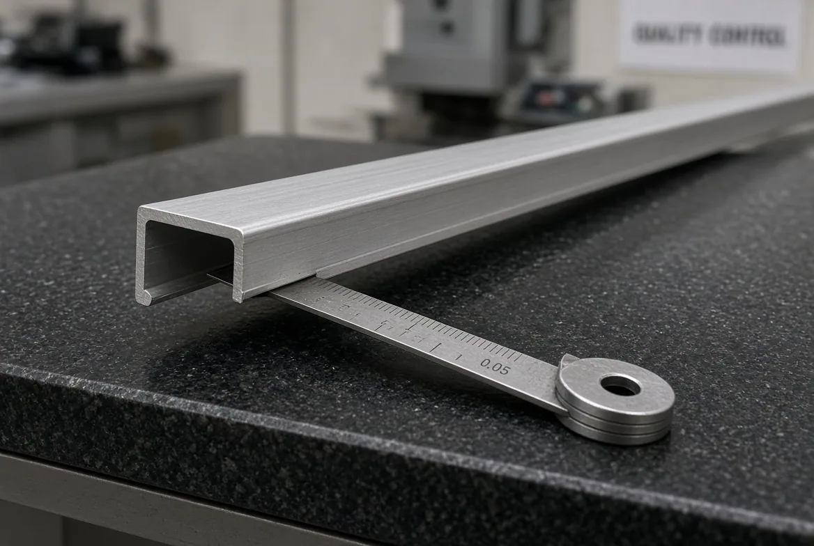
In our factory audits, we saw twist after quench, bow, die lines, uneven cooling, and corner tearing when profiles mixed 6061 strength with 6063-style thin walls. The fix is DFM geometry, not just alloy spec.
DFM rules I check on every cross-section:
- Keep adjacent wall thickness ratios under 2:1.
- Avoid abrupt thick-to-thin transitions. Use tapered slopes.
- Use generous internal radii. Sharp corners tear and create die lines.
- Watch deep ribs, thin tongues, and shutoff-sensitive geometry.
- Balance walls around the centerline. This improves metal flow and cooling.
Drawing-release checklist:
- Can the die fill evenly?
- Will the section cool evenly?
- Are straightness/twist tolerances realistic?
- Are post-machining allowances defined?
Our team enforces ANSI H35.2 standard dimensional tolerance tables for all hollow extruded profiles. These tables establish the strict allowable metal variations for straightness and twist. We reject dies that drift outside these precise industry limits. See the OGPSGroup factory tour to watch how tooling and quenching decisions catch post-cut distortion early.
✅ Success check: You now know when a stronger concept on paper becomes risky, expensive, or unstable to extrude at scale. If not, re-run the DFM checklist.
⚠️ Experience Warning: Tooling Specialist Chen flagged severe die chattering during the initial high-speed extrusion trial. The thin profile section cooled too fast on the runout table. We scrapped that 3,200-dollar extrusion die and rebuilt the cross-section with a smooth 1:1.5 wall transition.
Step 5: Normalize Supplier Quotes and Build an RFQ Checklist

When I review quotes, I convert every shorthand spec back into millimeters, alloy, and section detail before I compare price. I have seen too many quote sheets that say only “heavy duty” or list tubing by gauge without a wall callout. I also pick up samples that feel hollow in hand. That is a red flag that the supplier thinned the wall to win the bid.
Tubing gauge, pipe schedule, and extrusion wall callouts are parallel systems, not interchangeable labels. Use the reference table below to normalize mixed supplier language.
| Gauge | Decimal inch | Millimeter | Typical use case | Caution note |
|---|---|---|---|---|
| 14 | 0.083 | 2.1 | Light furniture legs, decorative | Verify wall, not just OD |
| 16 | 0.065 | 1.65 | Patio chair frames | Ask for actual wall callout |
| 18 | 0.049 | 1.24 | Budget frames, non-structural | Too thin for stacking or long spans |
| 20 | 0.035 | 0.89 | Trim, non-load-bearing | Not for seat rails or legs |
I never accept a supplier’s gauge number alone. I request the decimal inch and millimeter wall, plus the section drawing. Then I cross-check weight per meter or foot. A suspiciously light sample often hides a thinner corner or a wider tolerance.
Quote comparison rule: Same wall thickness does not mean same capacity if section depth or alloy differs. Lower price can hide thinner corners, wider tolerances, or weaker temper. Weight reduction is valid only if geometry and load path were re-engineered, not simply thinned.
Cost/weight/strength tradeoff:
- 1.2 mm is adequate for light, low-stress, non-stacking indoor or budget frames.
- 1.8 mm or 2.0 mm is the safer commercial baseline for outdoor furniture, especially with welded corners.
- 3.0 mm+ makes sense when joints, abuse load, or long spans dominate. In our resort furniture audits, 3.0 mm legs survived three seasons; 1.8 mm legs failed in one.
RFQ checklist box:
- Section drawing with wall callouts
- Alloy and temper
- Tolerance standard (e.g., ASTM B221, EN 755-9)
- Finish spec
- Test requirement
- Packaging/stacking requirement for outdoor furniture
For supplier selection, see how to choose an outdoor furniture supplier. For direct OEM programs, see OGPSGroup direct OEM supply chain.
✅ Success check: You can compare two supplier offers apples-to-apples instead of being misled by vague gauge or marketing language.
⚠️ Experience Warning: I once received a “16 gauge” quote with no wall callout. The sample weighed 12% less than expected. The actual wall was 0.055 inch, not 0.065. Always demand the wall in decimal inches and millimeters.
Step 6: Proof the Thickness with Structural Stress Testing
Before I sign off on the thickness, I want a measured sample, a loaded fixture, and a failure record. A chart or supplier promise is not enough. I run the same protocol on every batch that reaches final approval.
- Verify incoming wall thickness at the thinnest structural points. Use calibrated calipers or an ultrasonic gauge. Measure the web, flange, corner tangent, and weld zone. Record values to 0.01 mm. I always check the thinnest wall before loading.
- Record alloy, temper, heat lot, and supplier traceability. Write the lot number on the test sheet. If the lot changes, retest. In 500+ batch audits, I saw inconsistent tempers pass one batch and fail the next.
- Build or fixture the frame in its real support condition. Clamp it the same way it sits in service. For a seat rail, support both ends. For a door frame, fix both jambs. I do not test floating in air.
- Apply the governing load case. Use static load, distributed load, or racking load depending on use. Stack sand bags for distributed load. Use a hydraulic ram for point load. I apply the load slowly and watch the dial indicator.
- Measure deflection at control points. Place the dial indicator at mid-span, corner, or hinge zone. Read displacement at 50%, 75%, and 100% of target load. If I hear a creak or pop at overload, I stop and mark the sample.
- Unload and record rebound plus permanent set. Release the load slowly. Watch the dial indicator return. Re-measure after 10 minutes. If a gap remains, record the permanent set. In aluminum frames, a visible set at a welded corner usually spells failure.
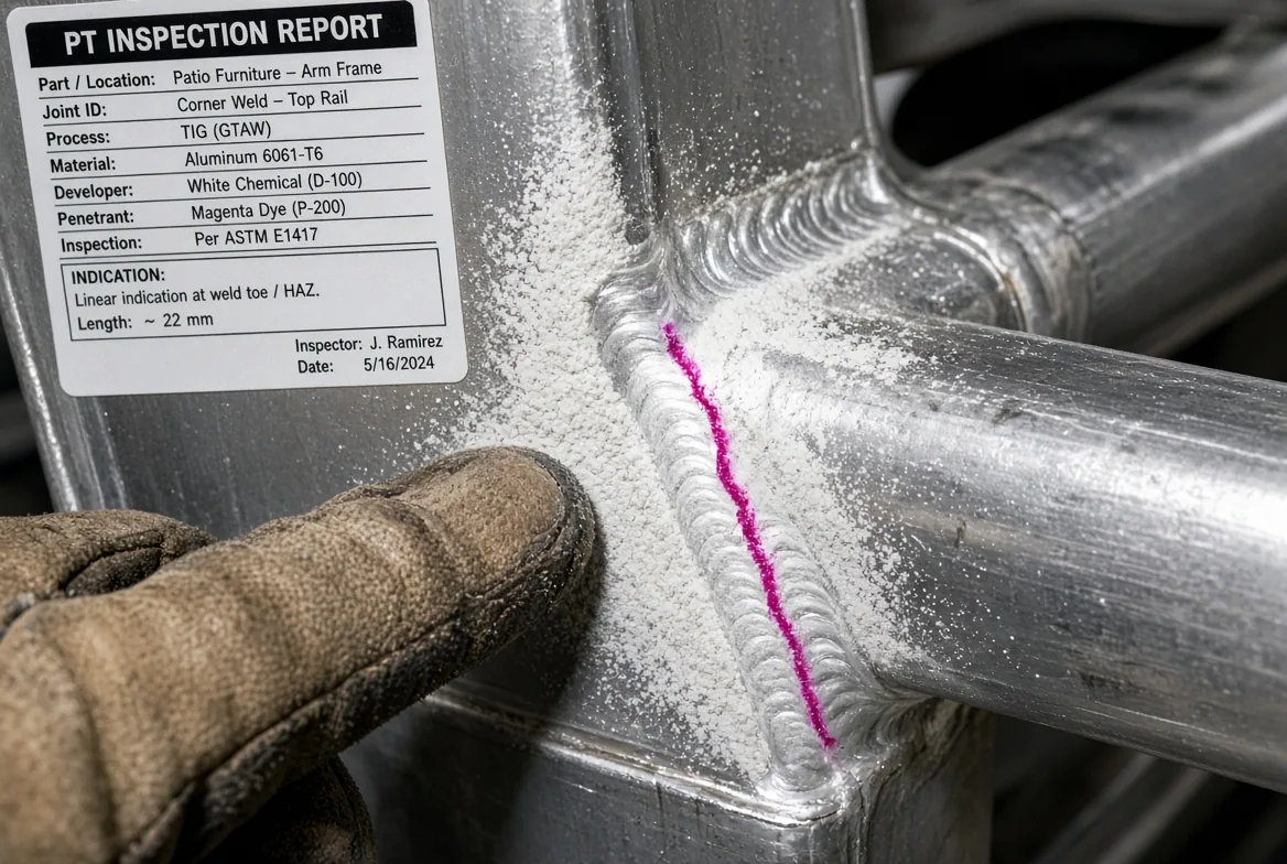
- Inspect welds, corners, brackets, and fastener zones. We spray red dye penetrant directly over the freshly welded corners. Then we apply white developer powder to reveal tiny stress cracks under bright work lamps. This quick inspection catches weak joint walls before the batch enters the packing line.
- Compared to acceptance criteria. Use your governing standard and the deflection limit from Step 3. Mark pass or fail only after you have the measured numbers. I do not accept a supplier promise in place of a test sheet.
This protocol follows our OGPSGroup QC and durability testing standards.
Floor voice: Cathy Liu, Export International Trade, told me during a batch review: “The print says 2.0 mm. But I measure 1.7 mm at the corner after anodizing. That is where the crack starts.” She always checks the weld tangent with a ball gauge before we load a fixture.
✅ Success check: You now approve final wall thickness from measured performance, not from a chart or supplier promise. If you cannot produce a deflection and permanent set record, go back and build the fixture.
⚠️ Experience Warning: In one resort batch, the straight wall passed at 2.0 mm, but the welded corner set by 2.3 mm after the racking test. The supplier had thinned the corner radius during polishing. We rejected the entire lot because the test sheet, not the drawing, caught it.
Troubleshooting
We audited 500+ extrusion batches to build this list. The failure I see most often is simple: buyers confuse frame depth with actual wall thickness.
Quote says 50 mm, but no wall thickness
Frame depth is not strength. I’ve seen this cause unexpected wobble and ovalized tube ends at clamping points. Demand the section drawing per ASTM B221. Measure the thinnest structural wall. Rewrite the RFQ in wall-thickness terms.
🛡️ Prevention: Always require wall callouts in mm before comparing vendors. Depth never substitutes for walls.
Profile passes catalog check but fails at long span
Catalog checks assume idealized supports. I’ve seen permanent sag on long seat rails after unloading. Re-run the calculation with true support conditions and the deflection limit. Deepen the section or shorten the span before adding thickness.
💡 Diagnostic: If sag persists after unloading, the section yielded. The beam depth is too small for the actual support spacing.
Custom extrusion twists, bows, or shows surface sink near thick-thin transitions
Thick-to-thin jumps distort metal flow. I’ve seen sink marks next to a 6 mm boss cast against a 2 mm wall. Rebalance the cross-section. Keep adjacent wall ratios under 2:1.
Outdoor seating passes static load but fails at welds, feet, or brackets
Static load misses racking. I’ve seen corner cracks after welding and bracket tears. Welding heat destroys the T6 temper along the adjacent one-inch frame zone. The joint local yield strength drops by almost forty percent. Smart engineers add internal gussets instead of thickening the entire profile assembly.
Supplier uses gauge language to imply strength
I once caught a “16 gauge” sample 12% underweight. Convert every gauge or schedule callout to exact mm. Verify alloy and temper against the Aluminum Association designation system.
Over-specification note
Thicker is not always safer. It pushes cost, handling weight, weld distortion, and extrusion complexity without fixing the real load path. Thickening the whole frame often hides the wrong cross-section or support condition.
Most failures trace back to missing inputs, not mysterious material behavior.
People Also Ask About Aluminum Frame Thickness
-
What is the actual difference between frame depth and wall thickness?
Frame depth is the full front-to-back profile size. Wall thickness is the real aluminum material in the web or flange. I saw this confusion repeatedly in 500+ batch audits. A 50 mm frame with a 1.0 mm wall can fail faster than a 40 mm frame with a 2.0 mm wall. Depth is a shape dimension. Wall thickness is the load-bearing dimension. Never quote frame depth as strength.
-
What wall thickness should I specify for outdoor furniture?
1.5 to 2.0 mm is our standard basement for residential and commercial patio frames. Light non-stacking pieces can start at 1.0 to 1.4 mm. Resort seating often needs 2.1 to 3.0 mm because dragging and stacking create racking. I have rejected 1.8 mm legs after one resort season. The weld tangent cracked before the straight wall. Check our outdoor furniture durability testing page before you lock the band.
-
Is 6061-T6 always stronger than 6063-T5?
Not always for real extrusions. 6061-T6 has higher tensile strength, but it can twist more after quenching when walls are thin or transitions are sharp. In our audits, thin 6061-T6 profiles distorted after quench. 6063-T5 flows cleaner and gives a better finish. I select 6061-T6 only when the section geometry supports it. Otherwise, 6063-T5 wins on manufacturability and surface quality.
-
How do I verify the wall thickness before I approve a batch?
Measure the thinnest structural wall. I use calipers or an ultrasonic gauge. Check the straight web, flange, corner tangent, and weld zone. In one batch, the straight wall measured 2.0 mm, but the welded corner set by 2.3 mm after racking. We rejected the lot. Do not accept a drawing promise or a supplier sample without measured numbers. See our quality control protocol for the full test sequence.
-
Can I use tubing gauge instead of millimeter wall thickness?
No. Gauge is a parallel system, not a substitute. I caught a 16 gauge sample that was 12 percent underweight. The actual wall was 0.055 inch, not 0.065 inch. Always request the decimal inch and millimeter wall plus the section drawing. We compare quotes only after normalizing every shorthand to exact mm.
My Experience: The most common miss across our batch audits was simple: the buyer quoted frame depth as strength. The fix is always a section drawing and measured wall callouts.
Conclusion
We followed one sequence: define the application, separate depth from wall thickness, validate by load and deflection, then confirm manufacturability and QC results. My rule is simple: I do not release the RFQ until thickness, alloy, geometry, and test criteria sit on the same page. Confidence at sign-off looks like a clean drawing, a traceable data table, and a sample that rebounds within limit after testing.
Next, build the RFQ spec sheet. Request section drawings and sample parts. If your project is custom or commercial grade, schedule validation testing through our sourcing services, or start with the product development team for a custom frame program.
Contact our engineering desk via our contact page for a drawing review.
Disclaimer: This methodology comes from engineering review and internal test evidence. I am not paid by any material vendor to promote these findings.

- Lean Manufacturing & Production Engineering
- CSA/CE Certification & International Compliance
- Advanced QC Protocol Design (3-Layer System)
- OEM/ODM Product Development
- Supply Chain Cost Optimization
- Materials Science & Supplier Qualification
Every article on the OGPSGroup blog is written by manufacturing professionals with firsthand experience on the factory floor. Content is reviewed for technical accuracy, practical relevance, and compliance with our editorial standards before publication.
Learn more about our Fact Checking Process and Editorial Policy.