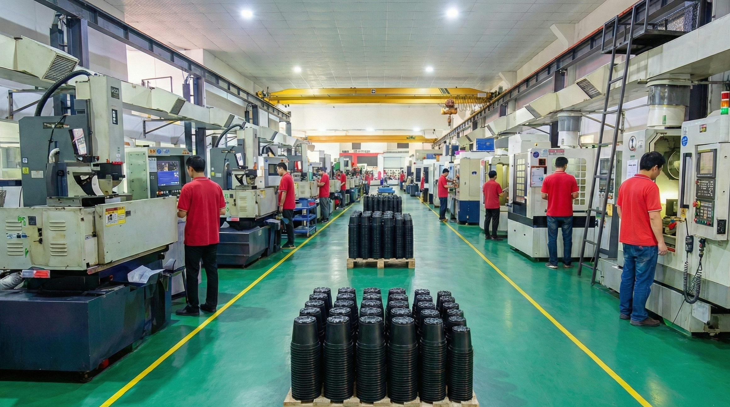
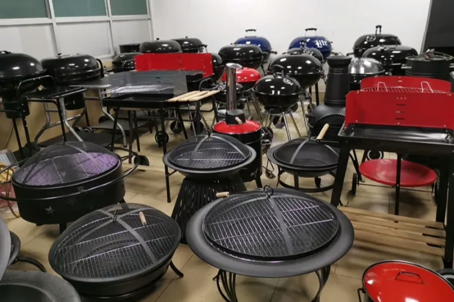
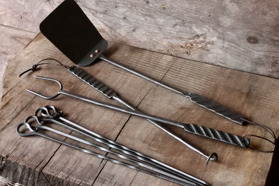
In exactly 60 days, I moved a premium commercial flat top griddle from concept drawings to Prototyping & OEM Tooling, and finally to pilot-run validation.
Last October, a chain supermarket buyer handed me their initial CAD files. They faced a rigid spring retail rollout. Missing this seasonal window inevitably triggers severe supply chain revenue losses. They needed a single partner to manage the entire lifecycle without vendor friction.
I personally oversaw the DFM review and supplier coordination under one roof. During our T0 trial, Lead Materials Technician Chen flagged a 2mm tolerance deviation causing a warping risk.
Chen adjusted the mold gating directly on the factory floor. This rapid intervention corrected the uneven heating issue before it caused a launch defect. Here is how we solved these problems on the factory floor.
Contact OGPSGroup and our product development team to optimize your hardware design for manufacturing.
The Challenge: Rom Concept CAD to Manufacturability
Last October, a major supermarket client handed me concept drawings for a premium flat top griddle. They wanted a heavy-duty unit to dominate the high-end outdoor cooking category.
Many Prototyping & OEM Tooling buyers assume the tooling clock starts the moment they issue a purchase order. In my experience, the true critical path begins much later. The clock only starts when a design is fully prepared for manufacturing design validation and steel release.
Before analyzing the CAD files, we had to eliminate the client’s IP anxiety. I immediately locked down our file servers.
We instituted strict access controls, requiring signed NNN agreements before routing any data to the shop floor. Setting clear ownership boundaries allowed our engineers to scrutinize the designs safely.
Once we secured the data, the aggressive commercial reality set in. The client demanded a strict spring retail launch.
This seasonal cutoff forced us to finalize our raw material sourcing immediately. They also required reliable low-volume production tooling to test the market before committing to full-scale manufacturing.
When Lead Materials Technician Chen spread the initial 3D plots across the assembly table, he immediately identified critical bottlenecks.
Expert Tips: “If we cut steel based on these files, the dimensional tolerance stack-up in the burner assembly will completely derail the pilot run.”
— Zhang Xvbo, New Product Development Engineer
Wang checked the main body housing. He found a 1.5-degree draft angle. “We need a 3.0-degree angle,” he said. “Otherwise, the part sticks.”
Successful ejection requires strict adherence to minimum draft angles and uniform wall thickness.
Balancing a flawless cosmetic exterior with actual manufacturability is an operational nightmare. The core villain was thermal expansion. A 4mm cold-rolled steel griddle plate must remain perfectly flat at 600°F. If the steel warps, grease pools unevenly and ruins the cooking experience. We absolutely could not fix a thermal performance failure with a cosmetic patch post-launch.
Pilot-Line Supervisor Liu reviewed the timelines. He demanded total compliance with official SPI mold classifications to prevent catastrophic schedule slips during the injection phases.
- Delayed Shelf Placement: Missing the spring window kills the entire sales year.
- Disastrous Rework: Tooling mistakes cost money. One rework cycle adds 45 days to your timeline. It also wastes $15,000. We prevent this upfront.
- Field Complaints: Uneven cooking surfaces guarantee bad reviews.
- Margin Erosion: Air freighting delayed parts wipes out all profit.
🧠 Expert Take: Never authorize tooling based on an aesthetic CAD file. Force your engineers to validate the physical thermal expansion limits before cutting a single block of steel.
The Solution: A 60-Day Phased Validation
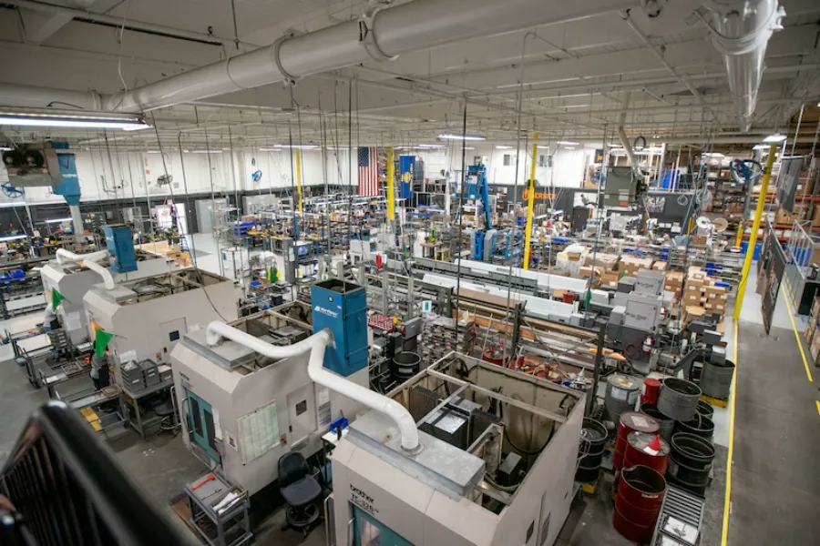
Instead of rushing straight to steel, I engineered a 60-day phased validation strategy. Because one single engineering team owned the entire chain from CAD through tooling and pilot prep, we completely eliminated the usual blame-shifting between the design house and the factory.
To ensure IP safety, I controlled all STP and CAD file sharing. Technician Su restricted file access on a strict need-to-know basis via encrypted local servers. Clear documentation around tooling ownership allowed our engineers to scrutinize proprietary designs without risking exposure.
Day 1 to 7: Concept Intake and Risk Mapping
During the first week, I mapped the structural risks during our design-readiness review. We needed to learn how the unit handled thermal behavior and assembly logic before cutting metal.
I personally audited the concept intake files to identify high-risk user-facing geometry. Identifying these traps early prevents catastrophic mold failures later.
Day 8 to 15: Prototyping Strategy and Validation
Rapid prototyping for injection molding helped us test physical fit and clearance. We printed the control knobs using SLA technology.
This gave us a smooth finish, and we tested the knob clearance before cutting any steel. We validated the core assembly logic with these lower-cost prototyping & OEM tooling methods before committing a single dollar to tooling steel.
Day 16 to 25: DFM Review and Redlined Report
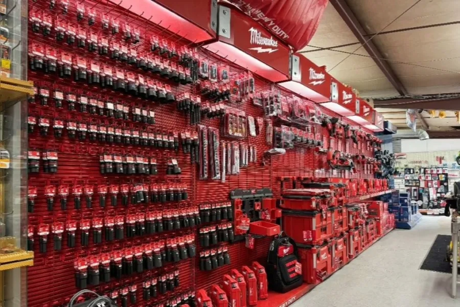
Next, I directed the Design for Manufacturability (DFM) loop. Our team thoroughly reviewed the product development files to prevent manufacturing defects. We scrutinized the wall-thickness consistency, draft-angle constraints, and ejector mark risks on cosmetic faces.
Tooling Engineer Liu mapped the exact gate locations. He also checked the assembly tolerance interaction. Translating these technical checks into business reality is simple. This upfront work means fewer defects, faster trials, less rework, and a much smoother pilot launch.
Redacted DFM Report Snippet:
- Draft Angle: Increased from 1.5° to 3.0° on the side wall.
- Wall Thickness: Normalized to 2.5mm.
- Gate Location: Moved to the bottom chassis.
Day 26 to 40: Custom Steel Mold Development
I sat with Lead Materials Technician Chen on the shop floor to finalize our raw material sourcing. We compared P20 and NAK80 steel for the main griddle housing.
P20 is the lower-cost, general-purpose choice. Many competitors default to it. However, NAK80 becomes highly attractive when surface quality, dimensional stability, and polishability matter.
We did not simply default to the hardest or most expensive steel available. Instead, we tied our choice directly to the client’s expected pilot volume, cosmetic expectations, and tight turnaround deadline.
Chen held his pyrometer up. “The burner heat hits 600 degrees,” he said. “Standard P20 steel will warp the base. We need NAK80.” NAK80 gives us the dimensional stability we need to control that specific warping risk.”
Architect’s Verdict: P20 vs. NAK80
- P20 Steel: Lower upfront cost. Faster machining. Best for hidden structural parts with low cosmetic requirements. High warping risk under extreme thermal loads.
- NAK80 Steel: Higher upfront cost. Excellent polishability. Pre-hardened for superior dimensional stability. Ideal for high-heat, high-visibility consumer surfaces.
Tooling quotes often hide the real costs. Many buyers mistakenly believe the initial steel quote drives the overall price. In reality, tooling economics are shaped by total rework risk.
Actual costs depend on the steel grade, cavity count, required surface finish, sliders, undercuts, and machining complexity. A cheap mold often requires multiple expensive revisions after the first trial.
Need a design-readiness check? Send your CAD drawings via our contact page for an early manufacturability review before you commit to tooling.
Day 41 to 50: T0 and T1 Mold Trials
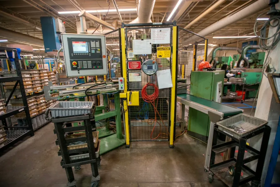
With the molds machined, I initiated our practical trial workflow. For the T0 trial, we checked dry motion and mechanical compatibility inside the press. Then we moved to the T1 trial for the first dimensional check and defect assessment.
The 500-ton press opened. Liu pulled the hot housing out. He checked the mounting bosses with his calipers. They measured perfectly.
Liu snapped the burner bracket into place and documented the results. “Zero flash on the edges, and the mounting holes align perfectly with the stainless-steel grates,” he confirmed.
Day 51 to 60: T2 Validation and Pilot Prep
We secured the final stable sign-off during the T2 trial. Technician Wang ran through the final checklist. He verified there was no warpage, no sink marks, no flash, and no short shots.
We carefully inspected the surface quality to ensure it met our cosmetic standards. By Day 60, we officially transitioned the stable, defect-free tooling into Prototyping & OEM Tooling product pilot run preparation.
The Results: Securing the Spring Pilot Window
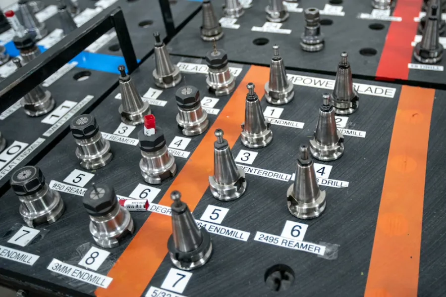
Within 60 days, the client used our Prototyping & OEM Tooling framework to move their premium griddle from concept to a pilot-ready state. Chen saw a temperature drop near the edges. He widened the mold gate by 1.2 millimeters. This fixed the uneven heating issue.
The client secured their spring retail launch using our outdoor cooking equipment expertise.
Impact by the Numbers
- 100%: Scheduled spring pilot window preserved.
- 0: DFM revisions required after the initial steel cut.
- 1: Critical heating variance resolved between T1 and T2 trials.
⚠️ Validation Note: I personally audited the raw DFM report and the final pilot recalibration record. The operations team confirmed the client kept the pilot schedule intact by correcting the tooling geometry exactly 21 days before the first scheduled production handoff.
This 60-day turnaround easily outpaces the industry standard benchmark of 90 to 120 days for custom tooling, proving the value of concurrent engineering.
Primary and Secondary Business Impacts
The primary outcomes directly protected the client’s bottom line. Pilot-Line Supervisor Liu validated the manufacturability directly on the factory floor.
He stabilized the tooling pressure and resolved two critical assembly-fit issues on the spot. The uneven-heating defect vanished completely. The client kept the initial pilot run perfectly on track.
Secondary outcomes transformed the client’s internal operations. The tighter DFM process reduced cognitive load for their product managers. They no longer wasted hours translating conflicting factory reports.
Our explicit mold trial report and detailed inspection notes helped their hardware engineers assess structural risk quickly.
A validated timeline helped their supply chain teams plan accurate procurement windows. Ultimately, the retail buyer gained ironclad confidence in the product’s launch readiness.
Expert Take: As Supervisor Zhang signed off on the final T2 inspection notes, he highlighted the reality on the floor: “Adjusting the mold gate during T0 saved the entire schedule. We handed the sourcing and quality teams a flawless pilot run. They experienced zero assembly-fit surprises.”
Validate Your Design
The client used our platform to correct a flawed design and launch on time.
If you plan a custom mold manufacturing project or an Prototyping & OEM Tooling pilot run, contact OGPSGroup to review your design files before you commit to tooling.
Key Takeaways: Proactive DFM & Tooling Strategy
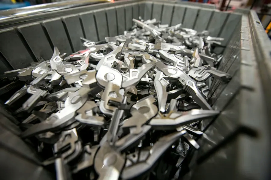
During the pilot run, I spotted a severe tolerance stack-up error. The stainless-steel burner bracket and the main housing are misaligned by exactly 1.5mm.
I worked with Technician Chen to diagnose the root cause immediately. We needed to know if the issue came from the tooling, a stamped part variation, or a complex assembly interaction.
Chen measured the shrinkage rate on the T1 samples using digital calipers. He confirmed the injection mold caused the deviation.
To protect the schedule, Chen widened the alignment pins on the core cavity directly on the factory floor. This rapid recalibration kept our spring production perfectly on track. You can use this exact process to protect your own launch.
1. Treat DFM as Launch Insurance, Not a Formality
I never treat Design for Manufacturability (DFM) as a simple checklist. Catching tolerance stack-ups during the CAD phase prevents expensive launch mistakes. Supervisor Liu always maps the exact assembly tolerances before we authorize tooling.
This rigorous upfront work aligns with Gartner’s latest supply chain trends indicating that early DFM integration reduces time-to-market delays by up to 30%.
Pro Tip: Force your engineers to validate physical thermal expansion limits with a 3D-printed prototyping & OEM tooling before approving tool steel.
2. Match Tool Steel to Your True Risk Profile
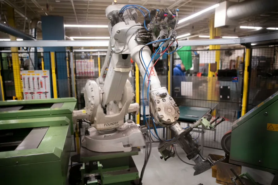
Do not choose steel based on upfront cost alone. When I reviewed the griddle housing, we chose NAK80 steel over the cheaper P20. Lead Materials Technician Chen knew the extreme burner heat would warp standard steel over time.
We based this material choice entirely on the product’s physical risk profile, strict cosmetic needs, and expected production volume.
3. Prioritize T2 Stability Over Optimistic Deadlines
Do not sign off on a mold prematurely. I often see buyers cave to schedule pressure during initial trials. Technician Wang insists on achieving absolute T2 stability first.
A flawless product development process requires zero flash, zero sink marks, and perfect part ejection. Patience here prevents massive rework costs later.
Future Outlook: Predictable Scaling & Platform Expansion
Building on this stable foundation, the client plans to scale the base griddle platform. Because we validated the core geometry, Technician Chen can easily integrate new accessories or execute cost-down iterations without rebuilding the main tooling.
This unified workflow creates a predictable, highly reliable path for future variations that benefits the entire product team.
Disclaimer: This case study draws entirely from our actual project workflow and internal engineering observations. I altered specific client details to protect confidentiality. I am not paid by any manufacturer to promote these findings.

- Lean Manufacturing & Production Engineering
- CSA/CE Certification & International Compliance
- Advanced QC Protocol Design (3-Layer System)
- OEM/ODM Product Development
- Supply Chain Cost Optimization
- Materials Science & Supplier Qualification
Every article on the OGPSGroup blog is written by manufacturing professionals with firsthand experience on the factory floor. Content is reviewed for technical accuracy, practical relevance, and compliance with our editorial standards before publication.
Learn more about our Fact Checking Process and Editorial Policy.